IPEIA: LFET Inspection for ID Corrosion in SAG-D Piping
Using Low Frequency Electromagnetic Technique (LFET) Southern Pacific Resource Corporation’s Senlac Thermal Project Facility
Regan L ‘Heureux’
Southern Pacific Thermal Project
Sunil Ramchandran
Pittsburgh, PA
Abstract
Sapphire Technologies Inc. has worked with numerous production facilities and pipe line companies that experience internal corrosion in various piping systems such as process piping, produced water, transmission lines and oil production lines. In this presentation we will discuss specific areas of a produced water disposal line describing what problems the line was experiencing and what solutions were implemented. We will discuss the non-destructive testing (NDT) methods used to locate and identify these flaws.A specific case study of a produced water line is detailed below.
The operations team from the Southern Pacific Thermal Project required a method of assessing the integrity of four lines within the plant, two of which had been suspended from service. The intent was to utilize these lines in preparation for a new pipeline project which is being constructed to supply new phases with Steam/Emulsion to maintain plant capacity. In order to gain a high level of confidence in the condition of the piping runs, operations expressed a desire to inspect a significant portion of the piping. At the time, it was their intention to perform profile radiography (RT) over approximately 26 meters of pipe with a significant portion of the piping being at a height greater than 3 meters.
It was suggested to operations that rather than radiography, Low Frequency Electromagnetic Technique be enlisted to perform the inspection. The obvious advantages are:
- No radiation exposure dangers
- Rapid inspection times
- Near 360° coverage
- Real time results
Introduction
Pipeline reliability is crucial for SAGD facilities. Forced outages can cost a company millions in lost revenue especially during periods of peak oil production. Non-destructive testing inspections before and during planned outages can prevent many of these forced outages. A good practice is to study the history of the pipelines and determine where to focus the inspections. The goal is to identify potential line failures and replace the sections during an outage. Another key is determining the cause of the failures in the line so the SAGD facility can then take corrective actions to prevent the corrosion from reoccurring. This specific case of where Non-Destructive Testing was implemented to help identify areas of corrosion and possible failure will be discussed. Sapphire Technologies Inc. used the Low Frequency Electromagnetic Technique (LFET) to perform this inspection along with ultrasonic thickness testing to prove up the flaw indications.The inspection results showed three of the four lines had little to no corrosion. The produced water line was found to have severe corrosion and needed replacing or repairs during the planned outage.
Nomenclature
- I.D – Inside Diameter
- LFET – Low Frequency Electromagnetic Technique
- UT – Ultrasonic Thickness Testing
- NDT – Non-Destructive Testing
- O.D – Outside Diameter
Body
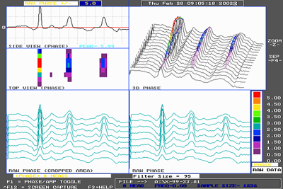
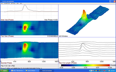
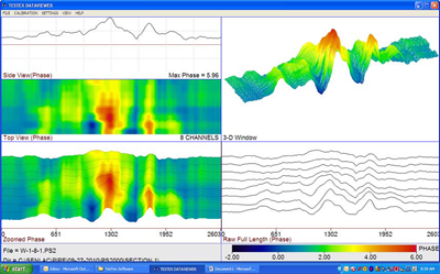
Sapphire Technologies Inc. uses a proprietary technology called “Low Frequency Electromagnetic Technique” (LFET) to inspect lines from the O.D. of the pipe. LFET injects an electromagnetic field into the test piece. The electromagnetic signal is measured. Any changes in the signal are noted and the distorted signals are compared to calibrations to determine the amount of wall loss. It detects I.D. and O.D. defects in ferrous and non-ferrous materials. LFET is a dry non-contact method based on the principles of electromagnetics. It is forgiving to uniform surface scale. The technology is adaptable to different applications and geometries which allows the inspection of different diameters of piping and elbows. A standard LFET pipe scanner has (8) channels and (16) pickup sensors. The system is lightweight, modular, and uses digital signal processing electronics while being operated with a laptop computer. The results are displayed in real-time with high-resolution color graphics 3D display.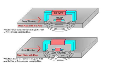
On April, 29, 2010, Sapphire Technologies Inc. (now a TesTex company) attending a meeting at SENLAC to demonstrate Low Frequency Electromagnetic Technique (LFET) to the onsite staff as it would apply to the scanning of piping, pressure vessels, tanks, and OTSG tubing.
During this meeting, the SENLAC staff expressed the need to conduct an integrity assessment on four runs of above ground piping. Two of these lines had been removed from service, and SENLAC’s desire was to determine if these lines could be re-commissioned for use in the upcoming pipeline project. These were the Steam and Emulsion lines.
Two other lines were currently in service, and SENLAC’s desire was to gauge these lines overall condition. These were the Produced H2O Disposal Line and the Skim Line. Both lines had a history of corrosion, and because the plant is continually adding phases to maintain plant capacity, these lines required an integrity assessment.
Historically, the produced water line experienced corrosion on its southern end, and SENLAC wanted to determine how far this corrosion may have run towards the northern end. The total length from the north to the south end is approximately 400 meters.
During discussions of how LFET would be applied to SENLAC’s piping systems, it was decided that SENLAC would remove insulation from various 3 meter sections of piping. Where the piping was within 1-2 meters of grade, no scaffolding would be necessary to conduct an inspection. Other sections of piping were close to 5 meters in the air, and for these sections, a man lift would be used to access the test areas.
SENLAC chose to use the LFET for the pipeline integrity verification and the inspection of all four lines was performed in May of 2010.
- Approximately 4.5 meters of the steam line were de?insulated and inspected 360° with LFET; there were no corrosion issues identified at the time of inspection.
- Approximately 4.5 meters of the emulsion line were de?insulated and inspected 360° with LFET; there were no corrosion issues identified at the time of inspection.
- Approximately 10.6 meters of the skim line were scanned 360° with LFET. Other than moderate pitting on the segment of pipe between T?305 and the repair patch, no significant corrosion was noted.
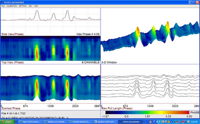
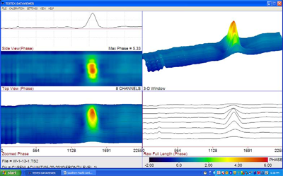
- Approximately 36 meters of the produced H2O disposal line were inspected 360° with LFET. Pitting was noted throughout the line up to the end of the first expansion joint, and primarily located at the 6:00 position. The pitting tended to be isolated, and the more severe pitting ranged in depth from 21% to 57% wall loss and a remaining wall of 6.08 to 3.3 mm. In total, 34 pits were evaluated and documented based on their severity in comparison to minor pitting noted throughout this portion of piping.
The scope of this project encompassed the inspection of a large length of the produced H2O truck?out line in response to a leak in the line. The leak resulting from through wall corrosion was noted in early September 2010 and a temporary patch applied.
The inspection was performed through the use of Low Frequency Electromagnetic Technique with pit depth verification via UTT.
In preparation for a piping replacement project, Southern Pacific elected to inspect this section and additional piping in an effort to identify other areas with severe corrosion.
Other Projects:
In addition to the work at SENLAC Sapphire Technologies Inc. recently complete 4 days of LFET pipe scanning at a at facility located near Cold Lake, Alberta. The local operator requested LFET scanning to be performed on several lines located inside their facility and a pipeline located outside of their facility.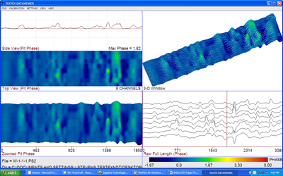
Conclusions
SENLAC, through usage of accepted nondestructive testing methodologies, was able to re-commission two out of service lines (Steam and Emulsion) in preparation for an upcoming pipeline project thus saving tens of thousands of dollars by not having to construct new Steam and Emulsion piping systems in the plant area. SENLAC’s choice to inspect and use the existing facilities resulted in effective use of capital as they continue the delineation if the resources.SENLAC was also able to gain confidence in the Skim Line to support it’s role in the plant expansion. The Produced H2O Disposal Line had areas of severe corrosion. SENLAC was able to gain a map of that corrosion and an understanding of how far the corrosion progressed from the disposal well. SENLAC was then able to conduct a piping replacement of the corroded sections and was able to salvage the rest of the disposal line again saving tens of thousand dollars far off setting the cost of the inspection services and the line replacement.
SENLAC also gained a map of the corrosion on the H2O Truck-Out Line and schedule the replacement and/or repairs of this section of the line.