Detecting Corrosion in Wellsite Oil & Gas Production Tanks
A low-frequency electromagnetic technique was used for detecting internal corrosion in above-ground storage tanks
By Daniel T. Schardine
Well site storage tanks are vital to the production of oil and natural gas. Typically at each oil or natural gas well site, gas and liquids are separated through the use of either a two or three phase separator vessel. The resulting dehydrated natural gas is sent through a pipeline to a treatment facility and the liquids are stored at the well site in production tanks. With the use of a two-phase separator, the oil (condensate) and water (produced water) are stored in a single tank where the produced water settles to the bottom. With the use of a three-phase separator, the condensate and produced water are stored in separate tanks. Production tanks are usually constructed in accordance with API Recommended Practice 12F (shop-welded steel) or 12P (fiberglass-reinforced plastic). A typical API 12F production tank is 8 to 12 ft. in diameter, 10 to 20 ft. tall, and holds 90 to 500 BBL (Barrels) of product. Metal tank shells are either 3/16 or 1/4 in carbon steel.
Localized corrosion is a major concern in production tanks. The constituents of the condensate and produced water are different at each well site and can vary significantly at locations very near to each other. Hydrogen sulfide (H2S), carbon dioxide (CO2), saltwater content, and micro-biologically induced corrosion (MIC) are a few of the major contributors to localized corrosion. Under the right conditions, through-corrosion can appear in production tanks in a matter of months. Production tank leaks can go undetected for extended periods due to the remote nature of oil and natural gas fields and lack of adequate leak detection means. In addition to the obvious environmental concerns, spill remediation and local and federal fines are some of the reasons for production spills to be avoided.
Accurate internal corrosion detection in production tanks is a challenge for oil and natural gas producers. Acquisition of spot ultrasonic thickness measurements is a good tool for discovering overall general corrosion trends in tanks, but is poor for detection of localized corrosion cells, determining accurate minimum thicknesses, and predicting areas of failure. internal visual inspections are largely infeasible die to a number of factors: prediction of tanks experiencing the most severe corrosion, costs associated with mobilizing tank cleaners, inspection crews, and safety personnel, and the inherent risk of confined space entry. Alternate means of internal corrosion detection are being explored for production tanks.
During a nine-month period in 2006, Premier NDT Services, LLC, located in Farmington, N.Mex, and TesTex, Inc., headquartered in Pittsburgh, Pa., partnered to inspect approximately 1500 natural gas well site production tanks using the low frequency electromagnetic technique (LFET) in the Anadarko basin, which is located in the Texas panhandle and western Oklahoma, for a major U.S. natural gas producer. Following is a description of LFET theory, the specific method of inspection used for this project, results obtained, and proof of testing procedure effectiveness.
The use of a low-frequency magnetic field allows for fairly uniform penetration throughout the thickness of a carbon steel test piece. This allows defects on both sides of the test piece to be detected. The frequency can be selected for best response on a variety of ferromagnetic and non-ferromagnetic materials and thicknesses. In carbon steel, LFET has been shown to be successful up to 3/4 in thickness. For in-service carbon steel with a thin paint of coating layer, LFET has been shown to have a practical upper thickness limit of 1/2 in. and, as expected due to the volumetric nature of the technique, flaw detection capability generally decreases with the increasing metal thickness.
The software developed to support LFET scanning provides a real-time graphical representation of the metal being examined for each sensor and over the entire scanned surface. Individual scans can be saved for later viewing and post processing.
For this project, the lower 16 in of the tank shell were scanned by the LFET method. The areas inaccessible to the scanner (directly around nozzles and weld joints, behind man way flanges, etc.) were inspected with ultrasonic thickness testing. The LFET scanner was connected to an instrument box that processed the signals and relayed them to a laptop computer for visual interpretation. An inspector manually rolled the scanner around the tank shell while an additional inspector monitored the computer for flaw indications. Upon identification of a flaw the scanner was rolled completely through the flawed area, and then the scanning direction was reversed to determine the specific area with the strongest flaw signal. The exact area of the flaw could be determined along the width of the scanner by the sensor channel with the strongest signal. This area was marked on the tank shell with a paint marker. The areas indicated were then subject to an ultrasonic thickness examination to determine the exact remaining thickness. A three person crew was capable of performing the LFET inspection, ultrasonic thickness prove-up, and documentation of three to eight production tanks per day depending on well site locations, findings, and weather.
Schardine, Daniel T., Detecting Corrosion in Production Tanks,Inspection Trends p19-21,Summer 2008
If you would like to learn more about our inspections, our systems, or how they can be used on your site, please contact us at 412.798.8990 or click here.
Localized corrosion is a major concern in production tanks. The constituents of the condensate and produced water are different at each well site and can vary significantly at locations very near to each other. Hydrogen sulfide (H2S), carbon dioxide (CO2), saltwater content, and micro-biologically induced corrosion (MIC) are a few of the major contributors to localized corrosion. Under the right conditions, through-corrosion can appear in production tanks in a matter of months. Production tank leaks can go undetected for extended periods due to the remote nature of oil and natural gas fields and lack of adequate leak detection means. In addition to the obvious environmental concerns, spill remediation and local and federal fines are some of the reasons for production spills to be avoided.
Accurate internal corrosion detection in production tanks is a challenge for oil and natural gas producers. Acquisition of spot ultrasonic thickness measurements is a good tool for discovering overall general corrosion trends in tanks, but is poor for detection of localized corrosion cells, determining accurate minimum thicknesses, and predicting areas of failure. internal visual inspections are largely infeasible die to a number of factors: prediction of tanks experiencing the most severe corrosion, costs associated with mobilizing tank cleaners, inspection crews, and safety personnel, and the inherent risk of confined space entry. Alternate means of internal corrosion detection are being explored for production tanks.
LFET Theory
The LFET method was developed by TesTex for detecting flaws on floors of above-ground storage tanks. The equipment used has since been developed to test a variety of plate, pipe, and tube. LFET works by injecting a low-frequency magnetic field into the test piece and measuring distortions in the field that occur over a flaw. The magnetic field is injected into the test with an external horseshoe-shaped driver. The driver is placed such that the return path of the field is through the area to be tested. Sensor coils placed beneath the driver detect changes in the magnetic field. A flaw or defect in the test piece causes the magnetic flux lines in that area to be distorted. This distortion can be measured as a change in phase and/or amplitude. Through the use of several sensors, a 3-D image can be regenerated from the collected data, and with suitable calibration, the shape and depth of the flaw can be determined. LFET does not require direct contact between the scanner and test piece and does not require the removal of thin surface coatings or small surface irregularities.The use of a low-frequency magnetic field allows for fairly uniform penetration throughout the thickness of a carbon steel test piece. This allows defects on both sides of the test piece to be detected. The frequency can be selected for best response on a variety of ferromagnetic and non-ferromagnetic materials and thicknesses. In carbon steel, LFET has been shown to be successful up to 3/4 in thickness. For in-service carbon steel with a thin paint of coating layer, LFET has been shown to have a practical upper thickness limit of 1/2 in. and, as expected due to the volumetric nature of the technique, flaw detection capability generally decreases with the increasing metal thickness.
The software developed to support LFET scanning provides a real-time graphical representation of the metal being examined for each sensor and over the entire scanned surface. Individual scans can be saved for later viewing and post processing.
Method of Inspection for Production Tanks
The natural gas well site production tanks in the Anadarko basin have a history of accelerated corrosion in the lower portion of the shell. The LFET method was chosen for its ability to pin point the most severe corrosion while the tanks were in service. An 8-in.-wide scanner was used for the inspection. The scanner was equipped with eight sensor channels evenly spaced along its width that could be monitored separately. The scanner was mounted on wheels so that the proper clearance between the scanner and tank shell could be maintained and to provide consistent scanning speed and technique.For this project, the lower 16 in of the tank shell were scanned by the LFET method. The areas inaccessible to the scanner (directly around nozzles and weld joints, behind man way flanges, etc.) were inspected with ultrasonic thickness testing. The LFET scanner was connected to an instrument box that processed the signals and relayed them to a laptop computer for visual interpretation. An inspector manually rolled the scanner around the tank shell while an additional inspector monitored the computer for flaw indications. Upon identification of a flaw the scanner was rolled completely through the flawed area, and then the scanning direction was reversed to determine the specific area with the strongest flaw signal. The exact area of the flaw could be determined along the width of the scanner by the sensor channel with the strongest signal. This area was marked on the tank shell with a paint marker. The areas indicated were then subject to an ultrasonic thickness examination to determine the exact remaining thickness. A three person crew was capable of performing the LFET inspection, ultrasonic thickness prove-up, and documentation of three to eight production tanks per day depending on well site locations, findings, and weather.
Results
Internal corrosion was indicated in approximately 90% of the tanks inspected, with the most severe corrosion occurring in the lower 8 in. of the shell. Typically, widespread general surface corrosion and isolated pitting corrosion were indicated. The corrosion was severe enough to warrant internal inspection or removal from service in approximately one-third of the tanks inspected.
Proof of Testing Procedure
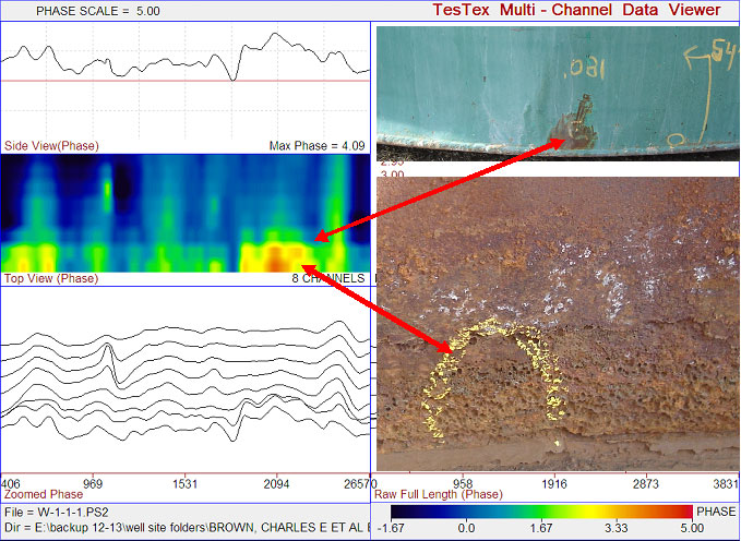
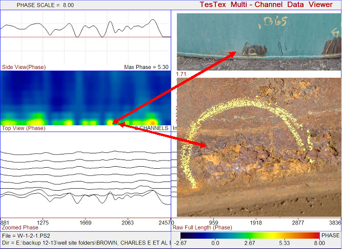
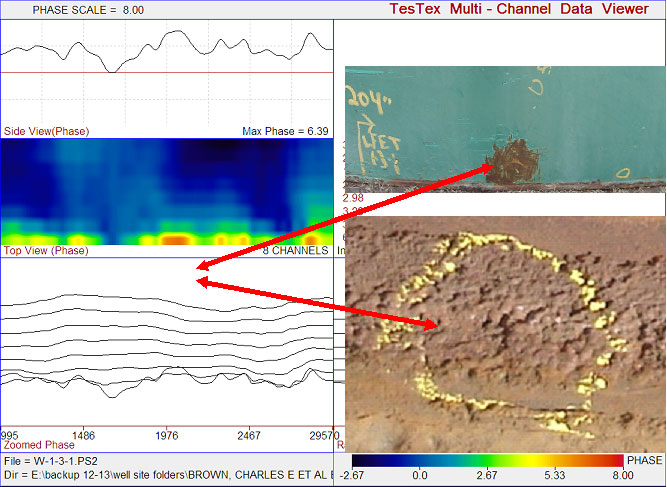
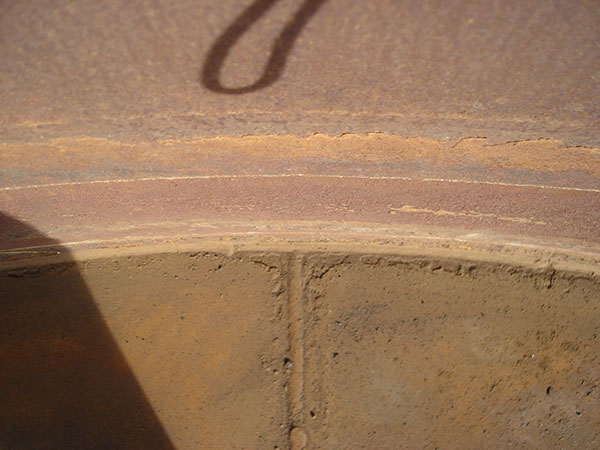
To investigate the effectiveness of the testing procedure, an inspected tank that had been taken out of service due to severe internal corrosion was dismantled for ease of internal inspection. The shell was cut circumferentially leaving the lower approximately 36 in. of the shell and floor intact. The lower shell was visually inspected internally and compared to the external inspection results. The internal surfaced of the floor and floor-to-shell weld were also inspected to determine the extent of corrosion damage relative to the shell corrosion damage. The external LFET inspection results indicated severe internal general surface and pitting corrosion in the lower shell. Three LFET scans were recorded and the lowest ultrasonic thickness measurements at the area of strongest flaw signal were recorded. The LFET scans and internal and external photos in figs 3-5. (in PDF version of article)Comparison of Internal and External Inspection Results
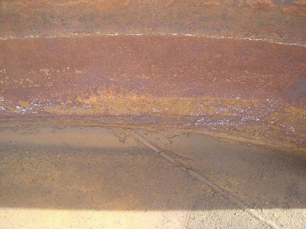
Figures 3-5 show that severe internal corrosion was present at the areas identified by the external LFET inspection. A complete internal visual inspection revealed widespread severe internal general surface and pitting corrosion throughout the lower 4 in. of the shell. This was consistent with the findings during the external LFET inspection. In addition, similar corrosion damage was observed on the shell-to-floor weld and on the floor adjacent to the shell-to-floor and floor plate welds. This finding underscores the need to perform internal inspections when significant internal corrosion is indicated by external inspection. Figures 6 and 7 are photos of the internal surfaces of the shell-to-floor weld and floor plates.Conclusion
The use of low-frequency electromagnetic technique (LFET) scanning with ultrasonic thickness testing prove-up is a reliable means of detecting internal corrosion in oil and natural gas well site production tanks. The major benefit is the ability to pinpoint areas of corrosion and determine remaining shell thickness while the tank is in service, sparing the time, expense, and risk of an internal inspection when it is unwarranted. All figures and images referenced can be viewed in the PDF version.Schardine, Daniel T., Detecting Corrosion in Production Tanks,Inspection Trends p19-21,Summer 2008
If you would like to learn more about our inspections, our systems, or how they can be used on your site, please contact us at 412.798.8990 or click here.