Improving Boiler Reliability through Non Destructive Testing
Shawn Gowatski
TesTex, Inc.
Pittsburgh, PA, USA
Abstract
TesTex, Inc. has worked with numerous utilities that experienced Boiler Tube Failures in areas such as water walls, superheaters, reheaters, etc. In this presentation we will discuss specific areas of a given boiler describing what problems (failures) the units were experiencing and what solutions were implemented. We will also discuss various failure mechanisms for boiler tubing, the causes, and various Non Destructive Testing (NDT) methods used to locate and identify these flaws. Some specific case studies of boiler tube failures are listed below.Xcel Energy-Valmont Station, Boulder, CO Boiler: This 166mw Coal Fired Boiler was experiencing water wall tube failures due to corrosion cells and hydrogen damage. This unit has been inspected with Low Frequency Electromagnetic Technique (LFET) four times over the last seven years. This unit has gone from experiencing tube failures every two weeks to only having 1-2 failures per year.
Western, PA Power Plant: This 835 MW Coal Fired Boiler was experiencing reheater tube failures due to oxidation pitting in their horizontal sections. Sections of this reheater were inspected with the Low Frequency Electromagnetic Technique using Low Profile scanners to access the bottom half of the tubes in the horizontal sections. Several flaws were found and repairs were made. Similar inspections were also performed in the plant’s other two boilers where no defects were found. These inspections helped the plant locate and make repairs to flawed regions in the boilers. Their run-time between boilers tube failures has risen significantly.
Introduction
Boiler reliability is crucial for power plants. Forced outages can cost a plant millions of dollars especially during periods of peak power demand. Non-Destructive Testing inspections during planned outages can prevent many of these forced outages. A good practice is to study the history of the unit and determine where to focus the inspections in the boiler. The goal is to identify potential tube failures and replace the sections during an outage. Another key is determining the cause of the failures in the tubes. The plant can then take corrective actions to prevent the defects from reoccurring. Two specific cases of where Non-Destructive Testing was implemented to help reduce boiler tube failures will be discussed. The first involves the inspection of the water wall tubes where corrosion cells and hydrogen damage were occurring. The second is the inspection of horizontal reheater tubes that were experiencing out of service corrosion. TesTex used the Low Frequency Electromagnetic Technique (LFET) to perform these inspections. The inspections that were provided improved the Time Between Failures for both plants.Nomenclature
- I.D – Inside Diameter
- LFET – Low Frequency Electromagnetic Technique
- MW – Megawatt
- NDT – Non-Destructive Testing
- O.D – Outside Diameter
Body
There are several Non-Destructive Testing technologies and inspections tools that are able to improve boiler reliability. There are (6) critical keys for using NDT to improve boiler reliability.1) The first key point is to explain your problems to the NDT Company. Be sure to describe the unit history, any major disruptions to the boiler operation such as the unit overheated, ran without water, or was laid up for an extended amount of time. Inform the company of the failure history including locations, frequency, and suspected root cause of the failures. Any metallurgical reports are also useful.
2) Provide the NDT Company with any drawings that you may have. Drawings of the unit with the problem areas identified are helpful in analyzing equipment needed and to estimate the amount of time the inspection will take.
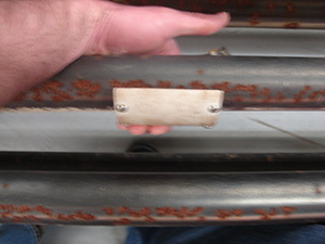
3) Provide the NDT Company with any tube samples that you may have. Samples allow the company a piece for their equipment to inspect. This allows them to fine tune the procedure to the boiler’s specific problems. The samples provide the technicians an insight on what the signals will look like for the particular failure mechanism the unit contains. The collected waveforms will help fine tune the calibration. Be sure to ask the vendor to detail their experience with your particular problem and the results of the past inspections.
4) During the early part of the actual inspection, the contractor needs to communicate with the plant on their findings. Some suspected defects should be removed to verify the inspection process, improve calibrations, and the accuracy of the calls. These samples will provide an actual comparison for the collected data. This will also provide confidence for the actual inspectors on what they are observing.
5) Make proper repairs. Try to repair as many of the defects as time and budget allows. 6) Take corrective actions to prevent and/or reduce future failures. Without taking corrective actions, the failure process may be reduced for a period of time, but the failures will resurface. Please remember that using NDT should improve your Time Between Failures. It will not eliminate all tube failures.
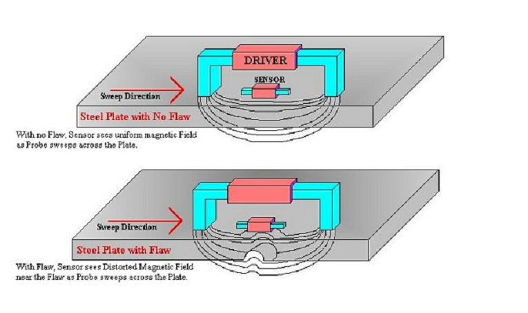
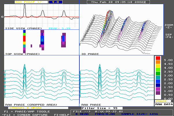
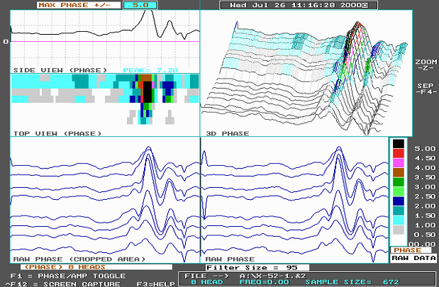
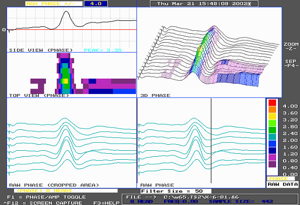
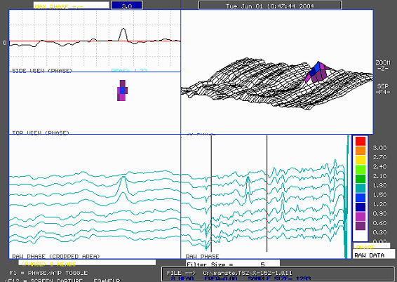
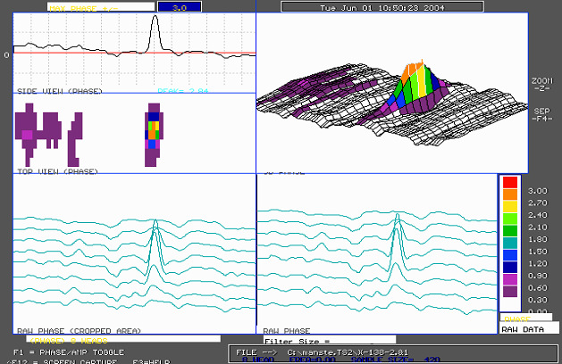
TesTex, Inc. has a proprietary technology called Low Frequency Electromagnetic Technique (LFET) to inspect boiler tubes from the O.D. of the tube. LFET injects an electromagnetic signal into the test piece. The electromagnetic signal is measured. Any changes in the signal are noted and the distorted signals are compared to calibrations to determine the amount of wall loss. It detects and quantifies I.D. and O.D. defects in ferrous and non-ferrous materials. LFET is a dry non-contact method based on the principles of electromagnetics. It is forgiving to uniform surface scale. This means the scanning requires the surface to be smooth but does not need to be sandblasted down to bare metal. A high-pressure water blast is usually sufficient in coal burning plants. The technology is adaptable to different applications, which allows the inspection of different diameters of tubing, the inspection of bends, and the inspection of tubes in space-constricted areas. A standard LFET water wall scanner has (8) pickup sensors and is able to inspect most of the hot side of the tube in one scan. The system is lightweight, modular, and uses digital signal processing electronics while being operated with a laptop computer. The results are displayed in real-time with high resolution color graphics 3D display.
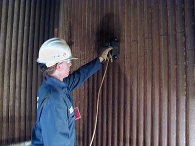
The Valmont Station had a planned outage in May 2000. Hard scaffolding was erected in the furnace and the tubes were cleaned with a high-pressure water blast. This method of cleaning removed the ash deposits and left the tubes with a uniform surface scale that allowed the LFET scanner to travel across smoothly. Please note the tubes were not sandblasted down to white metal. This saved time and money since LFET only requires the tubes to be smooth. As stated previously, LFET does not require any couplant nor a bare metal surface for a quality inspection. A total of 32,500 linear feet was inspected with LFET on four walls including the bullnose. Forty-five defects were found. Xcel Energy personnel inspected these defects with the Ultrasonic Ultrasonic Tangential L-Wave Velocity Shift method. This method confirmed hydrogen damage was present in several tubes. The tubes with hydrogen damage were removed. This inspection took a crew of eight men four days to complete.
Structural Integrity used the “Time of Flight Diffraction” (TOFD) technique to inspect the butt welds. Thirty-seven of the butt welds showed hydrogen damage. The tubes with hydrogen damage were replaced along with some tubes that showed severe wall thinning. After this inspection, the unit ran until the next planned outage in October of 2004 with only one tube failure due to hydrogen damage.
This inspection scope was repeated in April 2007. The LFET inspection, found 104 defects. The Ultrasonic Tangential L-Wave Velocity Inspection identified eighteen of the defects to have hydrogen damage.
The plant took the following steps to reduce boiler tube failures:
- Coated the Condenser Tubesheets
- Performed Eddy Current on the Condenser
- Chemical Cleaned the Boiler
- Chemistry Control
- Paid close attention to burner/fireball alignment
- Conducted Periodic Inspections
A power plant in western Pennsylvania experienced boiler tube failures in the horizontal reheater section in one of their boilers. The plant has three identically designed 835 MW coalfired Foster Wheeler Units. Tube samples near the failures showed I.D. pitting approximately 3/16” in diameter on the bottom side of the tubes. Due to the design of the reheater, access to the bottom of the tubes was very limited. The tubes were 2.5” O.D., 0.180” wall thickness, with the material being SA-213T22.
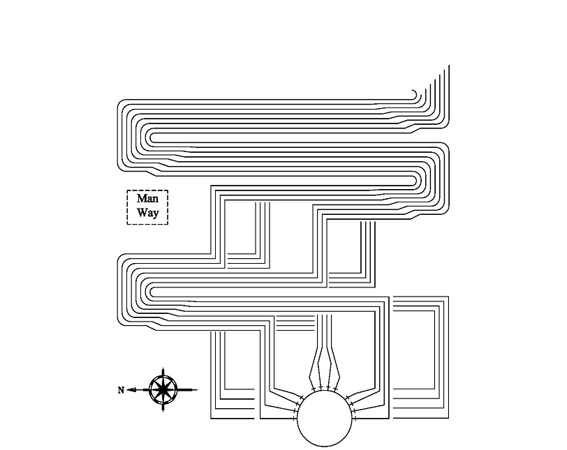
The inspection required a scanner that could fit between the tubes and be able to see pits as small as 3/16” in diameter. TesTex already had a Low Profile Scanner but the current design for the detection of a very small single pit was limited. A new LFET scanner with a double driver coil design was manufactured. The new scanner was able to see these small pits and through the use of calibrations was able to size the defects. Several scanners were manufactured for the upcoming outage.
The other two boilers were not experiencing failures in the horizontal reheater sections. The plant decided to go ahead and perform similar inspections on these units because they were of the same design. The same areas were inspected. No defects were found in either boiler.
Conclusion
Through the use of NDT, both of these plants were able to reduce costly forced outages. The plants identified their issues and worked with a vendor to improve the boiler run time. The end results are less plant down time due to equipment failure, less unscheduled maintenance, and less safety issues. The NDT inspections provided a more efficient boiler operation. The LFET inspections provided a fast, accurate, cost effective method to test the boilers.The keys to success in both of these cases were due to the plant accurately explaining the problem to the NDT Company. Tube samples and drawings of the unit were provided. Tubes were cut out during the inspection to verify results, improve accuracy, and provide confidence. The plants made the proper repairs. Collective actions were taken to prevent and or reduce future failures.
1 Linear footage is calculated by multiplying the numbers of tubes tested by the length. For example, 50 tubes tested at a length of 20′ per tube is 1000 linear feet.
Copyright © 2008 by ASME