ASNT Crack Detection Paper
Shawn Gowatski
TesTex, Inc.
Pittsburgh, PA
Introduction
The inspection of welds on piping, pressure vessels, columns, etc. is a major priority for plant personnel. Traditional methods such as magnetic particle, dye penetrant, shear-wave ultrasonics, radiography, and vacuum box testing are useful but all have some limitations. Most techniques require extensive surface preparation for a successful inspection. Radiography requires the area to be evacuated during testing which causes scheduling conflicts during an outage.The introduction of the Balanced Field Electromagnetic Technique (BFET) has made inspecting welds much easier with less unit preparation time. BFET is a scanning technology that detects cracking within 0.375” of the surface. The Balanced Field Electromagnetic Technique has inspected DA Tanks, Piping, Tube Stubs, Drums, Columns, Dryers, Heat Exchanger Shells, and other pressure vessels.
Explanation of BFET
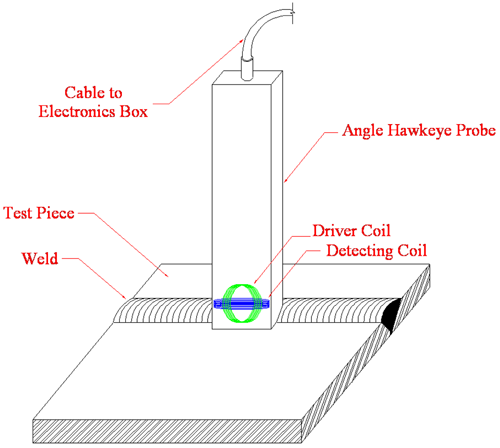
The Balanced Field Electromagnetic Technique was developed to enhance the signal responses produced from smaller defects such as cracks. In this technique, electromagnetic coils are wound and arranged in a balanced state. This balanced state is achieved by placing coils in both the “x” and “z” geometries at zero potential to each other. With the excitation coil in the “x” geometry and the sensor coil in the “z” geometry, a differential signal is produced over defected areas. In detail, the alternating current produced by the excitation coil is uniform and undisturbed when no defects are present. Conversely, the current is interrupted when a defect is present and forced to travel around it in a distorted fashion. It is this state of distortion that causes the coils to become unbalanced and thus producing an indication for the user that signals a defect. This signal response can be measured and through the use of proper calibration standards, a crack depth can be calculated. Another key to the balanced field electromagnetic technique is the ability to eliminate liftoff (and/or probe wobble) and noise from the signal. This is accomplished through a special algorithm in which these unwanted elements are rotated away from the main signal.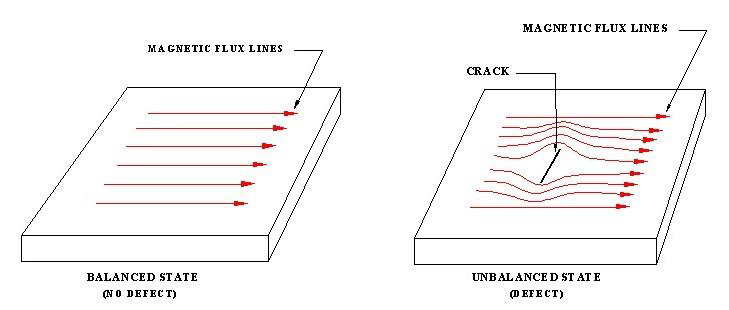
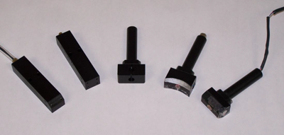
There are two different designs of BFET probes. The traditional Hawkeye probe is able to penetrate 0.125” into the metal which means surface cracks and sub-surface cracks that are within 0.125” of the surface can be detected. The coils in this probe are about the size of a pencil eraser which allows the probe to be shaped in different sizes and angles to meet the testing application. The second probe is called the HawkeyeDP (Deep Penetrating) which has a larger excitation coil that is 1.3” long. This probe is able to penetrate 0.375” into the metal which means surface cracks and sub-surface cracks within 0.375” of the surface can be detected. Probes can also be made of a ceramic material which allows the testing of units while online up to 500ºF. A special fabric can also be laid across the test area to help withstand the high temperatures.
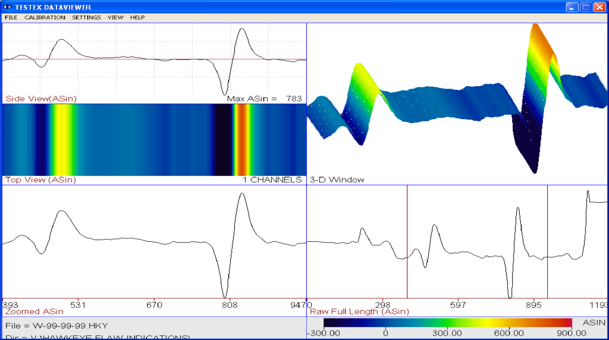
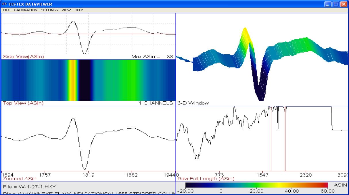
During an inspection, the data is viewed in real-time on a computer screen. This allows defects to be found and located during the data collection process which allows a plant to quickly prove-up any suspect defects and to schedule repairs without having to wait for the completion of the job
Applications of the Balanced Field Electromagnetic Technique
The Balanced Field Electromagnetic Technique has been used to inspect the welds on Pressure Vessels, Pipelines, Tank Floors, Tank Shells, High Temperature Lines, Expansion Joints, Tube to Header Stubs, etc. These inspections focus on the detection of cracking. The ConocoPhillips Refinery in Wood River, IL used the BFET systems extensively during their 2008 and 2009 turnarounds. Some of the units inspected included drums, columns, dryers, regenerators, separators, exchanger shells, piping, etc. The BFET systems have been used at numerous facilities throughout the world.The procedure for testing the units consists of visually inspecting the units for cleanliness. Remember with electromagnetic testing, the surface does not need to be polished, but it does need to be relatively smooth. Uniform scale and rust do not pose a problem for BFET. The next step is to make a determination on the ability to perform testing in the current conditions. If the conditions are safe and suitable for a successful inspection, the areas to be tested are identified and the components are labeled. A thorough visual inspection examining the test area for defects is performed. Once the system is setup, a minimum of three scans are performed on the welds. For welds with a wider weld profile, an increased number of scans are performed to cover the entire weld surface and the toe of the welds. Any suspect signals are retested and marked. Accurate measurements are recorded and the flaws are identified for reporting. A detailed report is generated after the completion of testing. During the Wood River Turnarounds, ConocoPhillips reviewed the reports and had a second on-site contractor company prove-up the indications using Magnetic Particle, Shear-wave Ultrasonic, or Phased Array Testing. At many other places, TesTex performs the BFET inspections as well as the prove-up inspections with a second technique.
Conclusion
The use of the Balanced Field Electromagnetic Technique has several advantages over the conventional testing methods. There is minimal surface preparation needed which reduces down time and costs involved in preparing the weld surfaces for testing. BFET can inspect through paints and coatings which provides more flexibility in testing. Surface and sub-surface cracks can be detected and quantified which provides a more in-depth understanding of the condition and integrity of the weld preventing any unforeseen forced outages. The faster testing speeds allow the inspection to be completed in a very short time frame, therefore providing quicker results and the ability for the plant to make timely repairs.The probes can be designed to reach limited access areas. Special probes can be made to inspect units online. The probes can also be made with a concave bottom to fit a specific pipe contour. The Balanced Field Electromagnetic Technique is a proven tool to help a plant assess the condition of the welds and for any other areas experiencing cracking.