Introduction to Magnetite Exfoliation
New supercritical boilers are designed with austenitic stainless steel boiler tubes in the superheat and reheat sections that operate at temperatures above 1005°F (540°C). At these elevated temperatures, stainless steel boiler tubes will produce magnetite on the inside surface of the tube. A typical arrangement of these tubes is shown in the picture below. When the boiler is taken off-line and the boiler tubes cool, the internal magnetite scale can exfoliate and accumulate in the lower tube bends. Large amounts of loose scale in the tube bends can block steam flow resulting in overheating and, ultimately, rupture of the tubes. Utilities experiencing exfoliation of new tubes have resorted to cutting the complete population of the affected tubes to remove any accumulated magnetite scale as a precaution against tube failure. Development of a reliable nondestructive examination (NDE) technique for identification of magnetite buildup in lower tube bends would benefit utilities experiencing exfoliation in stainless steel boiler tubes. TesTex worked with EPRI to develop a procedure to detect and roughly quantify the amount of magnetite in a stainless steel 347 tube.
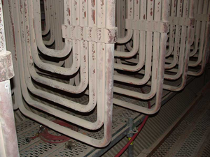
Pendant of secondary superheat outlet tubes
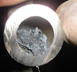
Magnetite flakes in lower tube bend
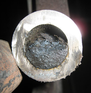
Wet magnetite flakes in lower tube bend
The unit contained 171 Assemblies with 12 Loops per Assembly. The customer requested more teams but due to the fact we only had two scanners, TesTex decided to send another team to work nights.
A total of 2052 loops were inspected. Boilermakers were provided by the client to spread the assemblies when necessary. Thirty-eight bends were found to have magnetite inside the tube. The client cut the bends out that contained magnetite. The magnetite was removed from the tube and then the bend was welded back into place.
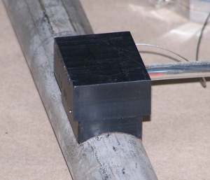
1.5″ LFET bend scanner
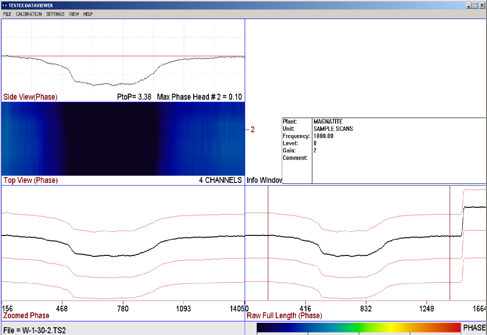
LFET waveform with 100% fill factor of magnetite. The waveform has a peak to peak phase response of 3.38°
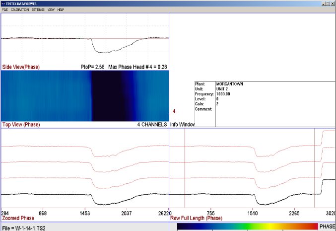
The Low Frequency Electromagnetic Technique waveform shown above contains 5 windows to interpret the data. The bottom right window shows the raw data as it was collected, and the bottom left window shows the data once it is zoomed in. The top left window shows a select channel of data and provides the phase response, and the middle left window is a simulated C-Scan. The top right window lists the equipment settings during the examination.
The LFET scanners used contain 4 LFET sensors spaced circumferentially alongside each other. The responses of the sensors are the 4 lines shown in the bottom two windows. When no magnetite is detected the sensors will provide a relatively flat line. When a magnetite deposit is encountered the signal will decrease due to the presence of additional metal. The signal decrease is directly proportional to the amount of magnetite detected. When wall loss is detected, the signal will increase. The simulated C-scan window changes to a darker blue where the magnetite is detected.
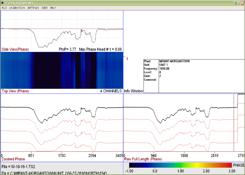
Here is an example from assembly 10, tube 19. The peak to peak phase response is 3.77˚ indicating a 100% blockage.
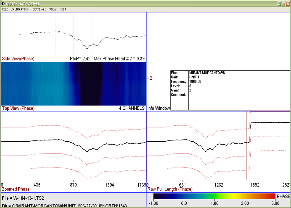
Here is an example from assembly 104, tube 13. The peak to peak phase response is 2.42˚ indicating a 40-50% blockage.
Since the initial emergency inspection, TesTex has worked with the plant to develop calibration standards to allow sizing of the amount of magnetite contained in the tubes. A study comparing the difference in the signal between wet and dry magnetite was also performed. A tube 30% full of magnetite shows a stronger signal response than a tube with 30% dry magnetite. This is due to the fact that the wet magnetite is able to be packed more densely in the tube. The study also showed that when a tube contains wet magnetite the response signal changes sharply when transitioning from an area containing no magnetite to an area with wet magnetite. The signal change for dry magnetite is smoother when transitioning from an area containing no magnetite to an area with dry magnetite. The following two waveforms illustrate the difference.
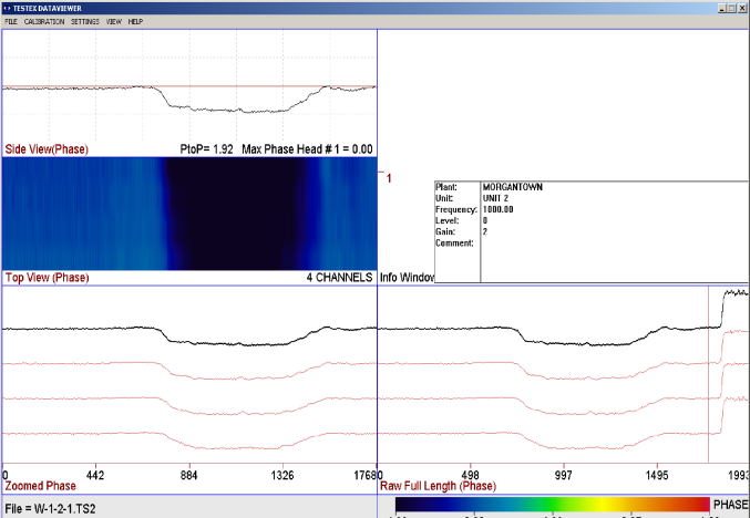
The waveform above represents 50 grams of dry magnetite
The waveform above represents 50 grams of wet magnetite. magnetite. Please note the sharp signal change at the transition point from the tube containing no magnetite to an area containing wet magnetite.
Calibrations shims have been machined from 10% to 80% full of magnetite. Data has been collected for each scanner for dry and wet magnetite. The plant has provided actual magnetite that was removed from their tubes which further improves the accuracy of LFET. This allows the technician to size the amount of magnetite in a tube during the collection process. The plant has purchased eight 1.75” LFET Bend Scanners to keep on-site to make sure the equipment is available when needed.
The plant has a sister unit that also recently had the superheater tubes replaced with the SS-347 material. TesTex inspected this unit when it became available and found over 300 bends containing magnetite. The unit had run approximately 7 months with the new tubes. TesTex has performed additional inspections on both units with less than 60 days run time and have found lesser amounts of magnetite. The follow-up inspections have shown about 30 bends that are 10-25% full of magnetite. A procedure has been developed to send 9 technicians to site to perform the inspection of 4104 bends in less than 12 hours using (4) two-man teams plus an analyst. A report detailing the findings is presented upon completion of the inspection.
TesTex has also performed some spot inspections for a customer in PA who has recently replaced their superheater tubes with SS-347 on two different boilers. The industry news of other utilities experiencing magnetite issues prompted them to perform the inspections. The inspection was focused on the pendants closest to the left and right sides of the boiler. No evidence of magnetite was detected in either boiler.
Field Trials
A field trial was conducted at Wisconsin Public Service in Rothschild, WI in the spring of 2009. EPRI issued a report detailing the results. Shawn Gowatski gave a presentation at the EPRI BRIG meeting in June 2009. TesTex received a call from a client in Maryland asking if we could perform an inspection to detect magnetite in their 1.75” OD, 0.240” wall, SS-347 superheater tubes. The unit had its second tube failure in 3 days and they needed a method to detect the blockage in the tubes. TesTex had manufactured special LFET scanners to inspect these tube bends for the EPRI trial. These bend scanners were for a 1.5” tube. TesTex ran a quick study in the lab and determined these scanners would work on the 1.75” OD tubes. We only had two of these scanners in stock. TesTex sent one team to the site and the customer put some magnetite in a tube that was removed for us to prove the technique was valid. We also performed a rough calibration onsite by filling a 2” section of the tube full with magnetite and also half-filled with magnetite. The responses were linear. The inspection frequency was 1000Hz and low power level was used. The magnetite causes the LFET signal to decrease due to it magnetic properties. It shows up as additional metal.The unit contained 171 Assemblies with 12 Loops per Assembly. The customer requested more teams but due to the fact we only had two scanners, TesTex decided to send another team to work nights.
A total of 2052 loops were inspected. Boilermakers were provided by the client to spread the assemblies when necessary. Thirty-eight bends were found to have magnetite inside the tube. The client cut the bends out that contained magnetite. The magnetite was removed from the tube and then the bend was welded back into place.
The LFET scanners used contain 4 LFET sensors spaced circumferentially alongside each other. The responses of the sensors are the 4 lines shown in the bottom two windows. When no magnetite is detected the sensors will provide a relatively flat line. When a magnetite deposit is encountered the signal will decrease due to the presence of additional metal. The signal decrease is directly proportional to the amount of magnetite detected. When wall loss is detected, the signal will increase. The simulated C-scan window changes to a darker blue where the magnetite is detected.
The plant has a sister unit that also recently had the superheater tubes replaced with the SS-347 material. TesTex inspected this unit when it became available and found over 300 bends containing magnetite. The unit had run approximately 7 months with the new tubes. TesTex has performed additional inspections on both units with less than 60 days run time and have found lesser amounts of magnetite. The follow-up inspections have shown about 30 bends that are 10-25% full of magnetite. A procedure has been developed to send 9 technicians to site to perform the inspection of 4104 bends in less than 12 hours using (4) two-man teams plus an analyst. A report detailing the findings is presented upon completion of the inspection.
TesTex has also performed some spot inspections for a customer in PA who has recently replaced their superheater tubes with SS-347 on two different boilers. The industry news of other utilities experiencing magnetite issues prompted them to perform the inspections. The inspection was focused on the pendants closest to the left and right sides of the boiler. No evidence of magnetite was detected in either boiler.