Corrosion Fatigue Cracking Paper
Section A: Introduction
Corrosion fatigue cracking is the leading cause of boiler tube failures. A tube failure due to corrosion fatigue cracking can be catastrophic and will usually bring a unit off line immediately. The cracking often occurs at an attachment or buckstay and starts on the inside diameter of the tube and propagates through the wall. Detecting corrosion fatigue cracks from the outside diameter is difficult due to the obstacles attached to the tubes. Radiography has had some limited success in detecting the corrosion fatigue cracks under optimal conditions but sizing of the cracks is challenging. Phased Array Ultrasonic Testing (PAUT) and the Balanced Field Electromagnetic Technique (BFET) can detect and size the cracking from the outside diameter if there are no attachments and there is access to the crack location.> TesTex was contacted by the Ohio Valley Electric Corporation/Indiana-Kentucky Electric Corporation (OVEC/IKEC) – Clifty Creek plant about developing an inspection tool to size known corrosion fatigue cracks in their boiler tubes. TesTex was confident their proprietary developed Balanced Field Electromagnetic Technique (BFET) technology could size the cracking if you could get an ID probe to the crack locations. BFET is based on electromagnetics which send an electromagnetic signal into the metal. A detector coil measures any disturbances in the signal and can size cracking within a 10% accuracy through the use of calibration standards.
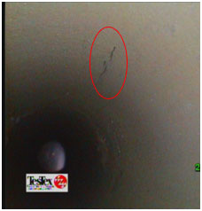
The corrosion fatigue cracking was located on the front wall tubes. The carbon steel tubes were 3.25” OD with a nominal wall thickness of 0.320”. The cold side of these tubes contained studs or dimples to allow refractory to stick to them. These tubes go from a 30” diameter mud drum up to a header approximately 25’ above. There are some bends in two of the rows near the mud drum. The locations of these cracks have been identified through a borescope inspection.
A rotating BFET probe had to be developed. During insertion, the probe needs to be in a contracted state and flexible to negotiate the bends. Once the probe is delivered to the desired location, the sensor arms need to expand out to the full ID circumference. Once expanded the BFET coils need to rotate circumferentially to bisect the corrosion fatigue cracks. These features proved to be challenging as the probe needs to be rugged enough to withstand the stresses of going through bends and also be able to collect clean quality data. The probes went through several revisions and field trials as it evolved into a dependable tool to perform the inspections.
The following pages will describe the inspection scope, the BFET technology, the developments of the system and the inspection results.
Section B: Explanation of Corrosion Fatigue Cracking
Annual surveys conducted by EPRI shows corrosion fatigue cracking to be the leading cause of boiler tube failures. Corrosion fatigue cracking is caused by cyclic stresses of a metal that is in a corrosive environment. Over time, small corrosive pits form on the inside diameter of a tube. These small pits eventually align to form cracks that will propagate through the tube wall. Corrosion fatigue cracks will often form at locations that restrict the tube from expanding and contracting during the thermal cycles. A common place to find corrosion fatigue cracking is at buckstays and other attachments to the tubes. The corrosion fatigue cracking is sometimes found in tubes with ligaments. These cracks originate on the inside diameter of the tube and are located on the crown of the tube or at the ligament.Corrosion fatigue cracking is often found in water wall tubes. These failures can occur as a weeper or as a full tube rupture on the cold side of the tube that can send a great amount of energy outward that can lead to catastrophic events. Due to this possibility, the industry focuses on eliminating these tube failures. Unfortunately corrosion fatigue cracking failures are increasing due to the constant cycling of boilers today to meet the energy demands.
The detection of corrosion fatigue cracking from the outside diameter of a tube is difficult due to the cracking often being at an attachment or buckstay. Radiography testing can sometimes detect the cracking if the system can be set up at the correct angle. This method has had some limited success in sizing the cracks under optimal conditions. The Balanced Field Electromagnetic Technique has been successful in detecting and sizing the cracks from the OD if the cracking is on the crown of the tube and there is access to scan the probe across the crack.
Section C: Explanation of BFET
The Balanced Field Electromagnetic Technique was developed to enhance the signal responses produced from smaller defects such as cracks. In this technique, electromagnetic coils are wound and arranged in a balanced state. This balanced state is achieved by placing coils in both the “x” and “z” geometries at zero potential to each other. With the excitation coil in the “x” geometry and the sensor coil in the “z” geometry, a differential signal is produced over defected areas. In detail, the alternating current produced by the excitation coil is uniform and undisturbed when no defects are present. Conversely, the current is interrupted when a defect is present and forced to travel around it in a distorted fashion. It is this state of distortion that causes the coils to become unbalanced and thus producing an indication for the user that signals a defect. This signal response can be measured and through the use of proper calibration standards, a crack depth can be calculated. Another key to the balanced field electromagnetic technique is the ability to eliminate liftoff (and/or probe wobble) and noise from the signal. This is accomplished through a special algorithm in which these unwanted elements are rotated away from the main signal.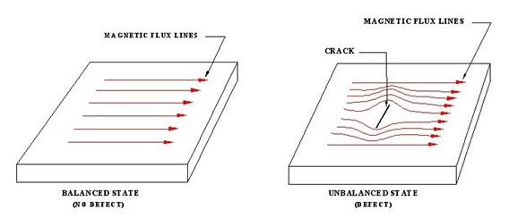
With the technology based on electromagnetics, a polished surface is not required. Quality readings can be acquired through coatings such as paint, epoxy, and rubber. The actual probe does not need to be in contact with the test piece. Sometimes the probe is placed in a small cart with the probe base set slightly above the test piece. The probe can be pulled quickly across the test specimen at a speed of up to 1 foot per second. The BFET method can test different types of metal by adjusting the test frequencies which range from 100HZ to 30,000HZ.
There are two different designs of BFET probes. The traditional Hawkeye probe is able to penetrate 0.125” into the metal which means surface cracks and sub-surface cracks that are within 0.125” of the surface can be detected. The coils in this probe are about the size of a pencil eraser which allows the probe to be shaped in different sizes and angles to meet the testing application. The second probe is called the HawkeyeDP (Deep Penetrating) which has a larger excitation coil that is 1.3” long. This probe is able to penetrate 0.375” into the metal which means surface cracks and sub-surface cracks within 0.375” of the surface can be detected. Probes can also be made of a ceramic material which allows the testing of units while online up to 500ºF. A special fabric can also be laid across the test area to help withstand the high temperatures.
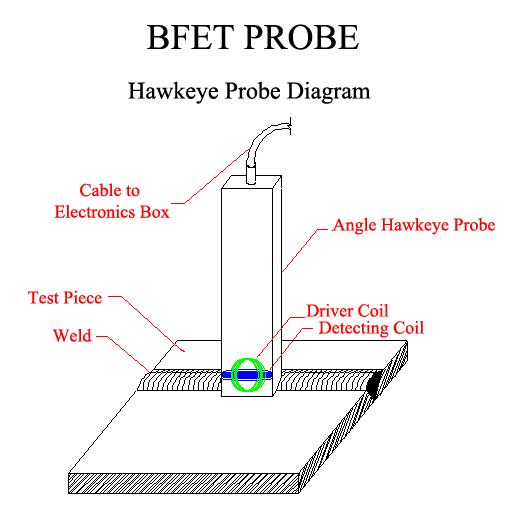
The standard probes have a flat bottom surface. This surface can be machined to contain a 45º angle to allow the probe to scan the toe of the weld. The surface can also be machined to a specific radius for the inspection of tube and pipe welds. Multiple Hawkeye probes can be placed in a rig to scan a wider area at a time. For example, grouping 8 Hawkeyes together will enable the system to scan a 4” wide area per test sweep. The probes can also be mounted in an arc for the inspection of piping that has suspected cracking along the length of the pipe.
During an inspection, the data is viewed in real-time on a computer screen. This allows defects to be found and located during the data collection process which allows a plant to quickly prove-up any suspect defects and to schedule repairs without having to wait for the completion of the job.
The Balanced Field Electromagnetic Technique has been used to inspect the welds on Pressure Vessels, Pipelines, Tank Floors, Tank Shells, High Temperature Lines, Expansion Joints, Tube to Header Stubs, etc. These inspections focus on the detection of cracking. Several plants use the BFET systems extensively during their outages. Some of the units inspected included drums, columns, dryers, regenerators, separators, exchanger shells, piping, DA tanks, socket welds, etc. The BFET systems have been used at numerous facilities throughout the world.
Section D: Inspection Scope
The OVEC/IKEC Clifty Creek plant has six identical B&W Open Pass Boilers producing a total of 1.3GW. The plant was constructed in the 1950s and was originally used for supplying power to the Department of Energy. Their contract expired in 2003 and the plant began supplying power publicly. Since 2003, the units have been subject to cyclic loads.The boilers have been experiencing tube failures on the front wall due to corrosion fatigue cracking. The plant began conducting borescope inspections to identify areas with cracking, and originally set criteria to remove all cracks that were longer than 3” in length. The units contained several cracks longer than 3” and it was found that most of the cracks removed were not significantly deep.
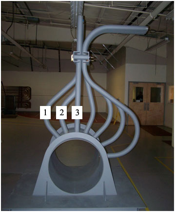
The front wall tubes are 3.25” OD with a 0.320” nominal wall thickness. The tube material is carbon steel and the OD surface of the cold side of the tube has studs. Access to these tubes is through a 30” diameter mud drum. The tubes go up to a header approximately 25’ above. There are three rows of tubes that come out of the mud drum to form the front wall containing a total of 112 tubes. The first row is a straight tube, the second row has two small bends, and the outside row has a larger sweeping bend. The corrosion fatigue cracking was located above the bends.
The plant provided TesTex with a list of tubes that contained cracks that were found through the borescope inspection. The location of the crack was provided by a distance from the mud drum. The accuracy of the crack location is plus or minus two feet.
The inspection tool would be inserted into the tubes at the mud drum. The probe needed to go through the bends and travel up approximately 25 feet, and measurements would be taken over a 4’ length. Any cracks found to be 35% deep or greater would be removed.
Section E: Sensor Development
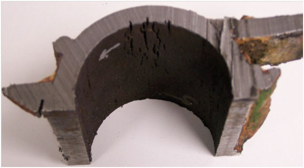
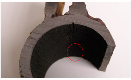
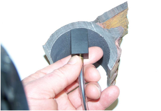
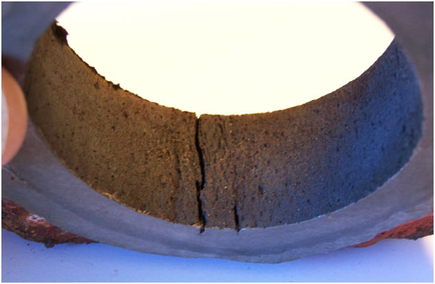
TesTex received several boiler tube samples from the OVEC/IKEC Clifty Creek Station that contained corrosion fatigue cracking. The carbon steel tubes were 3.25” O.D. with a nominal wall thickness of 0.340”. TesTex was asked to perform a “Proof of Concept” that their “Balanced Field Electromagnetic Technique” (BFET) technology could successfully size these cracks.For the “Proof of Concept”, TesTex focused on showing the BFET sensors could successfully size the cracks. Since the Corrosion Fatigue Cracking is surface breaking, the traditional Hawkeye design was used. TesTex selected three tubes samples that showed cracks and had the samples split open. TesTex also selected a section of tubing with no visible cracks. This clean section of tubing was used to machine calibration standards.
The clean section selected for the calibrations were 10” long and was split in half. For identification purposes, one section was labeled #88 and the second section was labeled #99. EDM notches were machined into the two sections. Sample #88, had EDM notches with a width of 0.020” at depths of 20%, 40%, and 60%. Sample #99 had EDM notches with a width of 0.040” at depths of 20%, 40%, and 60%.
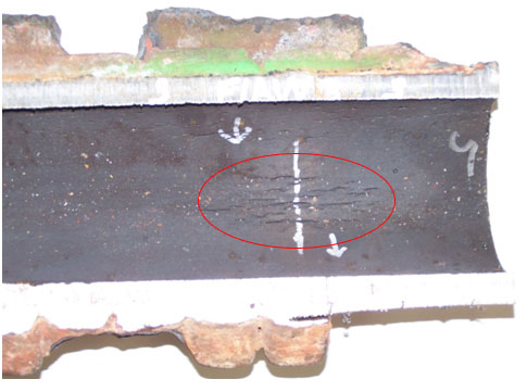
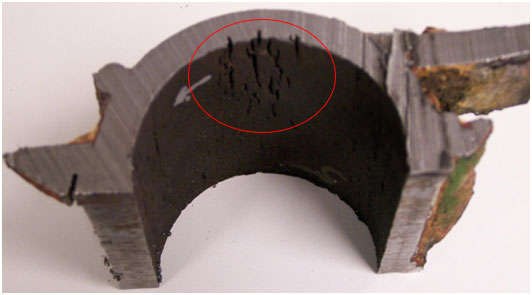
Three field samples with cracks were chosen for the study. The first sample contained a single crack that was approximately 0.050” wide at the surface and approximately 1” long and was labeled sample 1. The second sample chosen contained a single crack that was approximately 0.035” wide and approximately 2” long and was labeled sample 2. The third sample contained a series of three cracks that was spaced tightly together and was labeled sample 3. The cracks in this sample were approximately 2” long and approximately 0.035” wide at the surface.

TesTex manufactured three Hawkeye probes with a radius of 1.30” for the testing of the samples. Each probe contained a different size coil. The pick-up coil diameters used were 5.8mm, 7.4mm, and 9.5mm diameter.
The first round of testing used the three pick-up coils to test the two calibration standards and the defect in Sample 1. Each probe was tested at thirteen frequencies ranging from 200Hz to 950Hz. This was performed to determine the proper frequency to perform the inspections and to also determine the proper probe coil diameter to use. Once the tests were performed, Sample 1 was sectioned at the scan location and the depth of the crack was measured to be 0.094” deep out of a nominal wall thickness of 0.345” which translates to a crack depth of 27.2%. The probe with the 5.8mm diameter coil correctly measured the crack depth at a frequency of 400Hz, 450Hz, and 750Hz. For the 7.4mm probe, the crack was correctly measured at a frequency of 850Hz, and the 9.5mm probe was correctly measured at 200Hz, 250Hz, 300Hz, 350Hz, 400Hz, 450Hz, and 750Hz.
A second round of testing was performed at the successful frequencies for each probe on Samples 2 and 3. After the data was collected, the samples were cut across the crack to measure the depths. The crack in Sample 2 was measured to be 0.078” deep out of a nominal wall 0.341” which translates to a 22.9% crack depth. The deepest crack in Sample 3 was measured to be 0.093” out of a nominal wall of 0.340” which translates to a 27.4% depth. The 5.8mm diameter probe successfully sized the cracks in Samples 2 and 3 at a test frequency of 450Hz. The probes with the 7.4mm and 9.5mm diameter coils seemed to have difficulty in sizing Sample 3 that had the 3 cracks together. These two probes appeared to average some of the cracks together. The smaller probe with the 5.8mm diameter coil was able to see the individual crack signals.
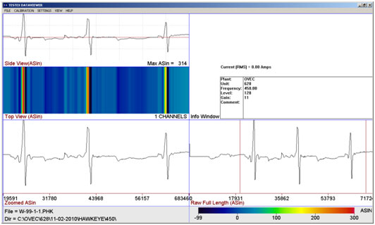
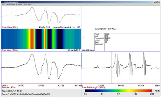
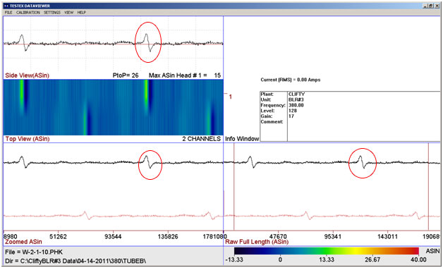
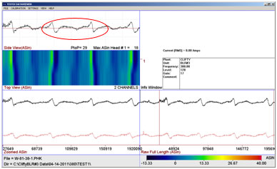
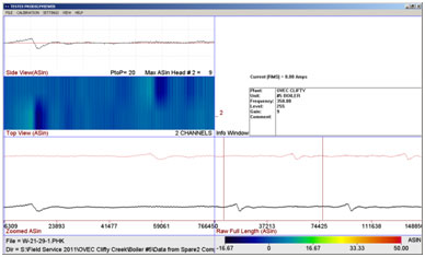
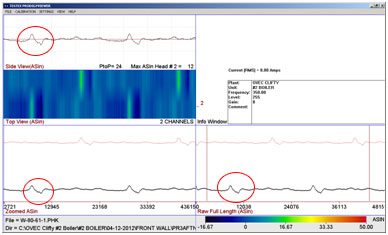
Waveforms for the probe with the 5.8mm diameter coil at a test frequency of 450Hz are shown below.
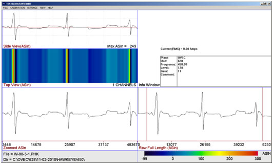
The above waveform shows the data in five different windows. The bottom right window shows the raw data as it was collected. The bottom left window shows the zoomed in view of the data which allows you to focus on a certain section of the waveform. The middle left window is a simulated C-scan and the top left window shows the zoomed in view of the waveform and also provides a measurement of the Asin signal. The top right window lists the testing settings.
If the data was collected on a clean section of tubing, the waveform would be a relatively flat line. The sharp up/down signal is where the coil went over a crack-like defect. This particular waveform in Figure 11 scanned across a 60% deep EDM notch, 40% deep EDM notch, and 20% deep EDM notch. These notches had a width of 0.020”. The signal is strongest for the 60% notch and weakest for the 20% deep notch. This data provided us with calibration tables to compare the actual flaws tested to calculate an actual depth. An accuracy of plus/minus 5% was used to determine if the crack was sized correctly.
The Balanced Field Electromagnetic Technique (BFET) proved in can size these cracks. The traditional style Hawkeye probe with a machined radius to fit the ID of the tube is ideal for the ID surface breaking corrosion fatigue cracks. A smaller 5.8mm diameter pick-up coil can size single cracks and can also see individual cracks that are located next to each other.
Additional tests were performed once the probe was built and the 5.8mm diameter sensors were placed on the rotating probe. Some additional samples were tested at several frequencies. The samples were then split open and destructive measurements were taken. The probe accurately sizes the cracks at frequencies ranging from 300Hz to 450Hz.
Section F: INITIAL PROBE DEVELOPMENT
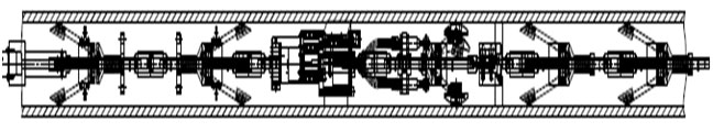
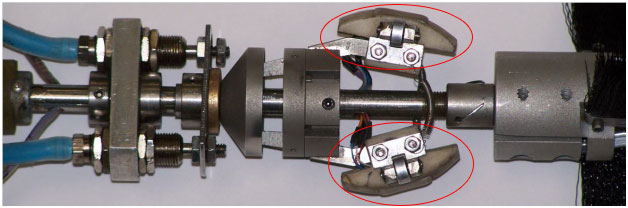
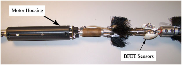
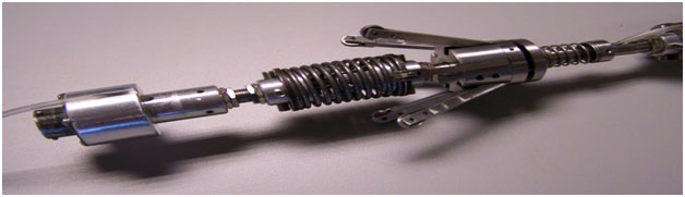
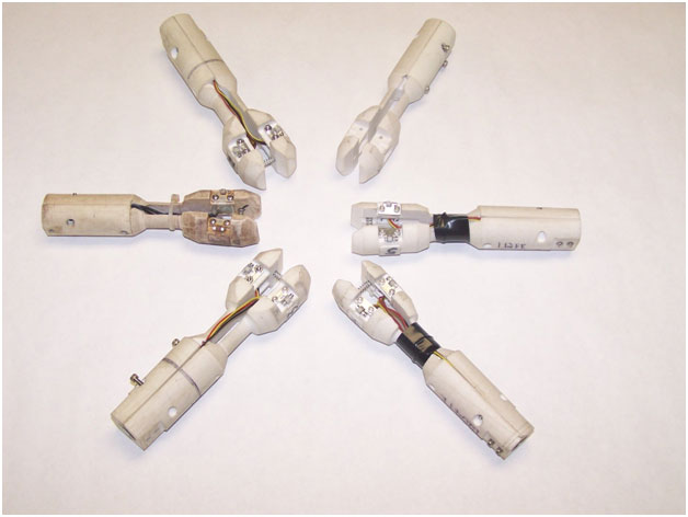
The probe needed to be flexible in order to be pushed through the mud drum bends. It was also necessary for the probe to collapse to a smaller diameter when being pushed into the boiler tube and pulled out of the tube. Once the probe is pushed into a desired location, the sensor heads need to expand out against the tube and then rotate circumferentially to record reliable data.The probe was designed in several pieces which were connected with small universal joints. The probe contained 4 sections with fingers that were used to help keep the probe centered in the tube. A motor and slip ring were housed in aluminum housing. The function of the motor is to rotate the BFET coils circumferentially around the ID of the tube. Without a slip ring, the wires would twist off. The slip ring is comprised of two parts, a stationary part and a rotary part which allows a continuous electrical connection between the stationary back part of the probe and the rotating sensor heads. Once the probe is pushed to the desired test location, compressed air is inserted into the air hoses which connect to air cylinders that expand the sensor arms out against the tube wall. After the sensor arms are extended the motor is turned on and the arms are rotated circumferentially around the inside diameter of the tube. Once the data is collected, the motor is turned off and the air is released from the air hose which contracts the sensor arms. The probe is then retrieved from the tube.
The probe is connected to a hard flexible poly. This poly is strong enough to push the probe upwards into a tube. An aluminum cover piece goes over the poly to probe connection point.
The plant provided TesTex with some tubes that were bent to simulate the actual bends the probe would encounter during the inspection. Upon completion of the probe, TesTex attempted to push the probe through these samples. The probe successfully went through the longer sweeping bend but would not go through the tube that contained two bends. This trial was just days before the initial field inspection. This initial inspection was mainly a practice run as the tubes were being replaced after the inspection. It was decided to still go through with the inspection focusing on the row of straight tubes and also the long sweeping bend.
Section G: Electronics Development
The BFET probes were traditionally used with a TS2000 Electronic System. This system has a maximum collection rate of 155 samples per second per channel. Unsteady scanning speeds of the BFET probes can distort the signal at these sample rates. TesTex was able to develop an electronics called the “Prodigy II” that has collection rates of 32 times the test frequency which is approximately 300Hz for the testing for corrosion fatigue cracking. This test frequency enables the system to collect 9600 samples per second per channel of data. This collection rate eliminates the concerns of any unsteady scanning speeds.The Prodigy II also allows the gain and rotations of individual channels which helps in optimizing the probe. With the old TS2000, an average gain and rotation would be used for all channels.
A motor control box was designed to allow the operator the run the motor at 12 volts or 24 volts. The 24 volt option rotates the probe twice as fast. The control box also has a knob to control the intensity of the LED lights that aided the video cameras that were mounted on the probe. The purpose of the video cameras was to allow the operator to see whether the sensor arms were expanding and rotating correctly inside the tube.
Section H: Inspection of Boiler #6
On March 7-8, 2011, TesTex, Inc. examined some of the #6 Wall Tubes at the OVEC/IKEC Clifty Creek Station in Madison, IN. Six tubes were inspected with the newly developed Balanced Field Electromagnetic Technique (BFET) probe that was funded by the Clifty Creek Station. The carbon steel tubes are 3.25” OD x 0.350” wall thickness. All 6 of these tubes came straight up from the drum and contained no bend. The inspection focused on sizing corrosion fatigue cracks that had been observed with a borescope in the summer of 2010. The length of the cracks was noted to be less than 3” in length. The crack location was provided to TesTex in a length measured from the mud drum with an accuracy of plus/minus two feet. TesTex inspected these tubes over a length of 4’ with the location provided being the midpoint. Several small cracks were observed with the BFET system. All cracks found were measured to be less than 25% in depth.The Balanced Field Electromagnetic Technique probe contains two sensors that are positioned 180˚ apart. Once the probe is positioned to the proper elevation, the arms containing the sensors are expanded using small air cylinders. After the probe arms are expanded, a motor spins the sensors around the ID of the tube. The sensors bisect the cracks and the crack responses are recorded. The crack responses “Asin” values are then measured and compared to a calibration curve that is produced from scanning known depths of EDM notches. The depth percentages provided assume the tube has a wall thickness of 0.350” at the test location. The Asin responses for both sensors are recorded.
TesTex attempted to insert the probe into several tubes that contained the smaller bend. Most of these tubes contained a butt weld in the middle of the bend. The probe could not go around the bend. A few tubes without this weld were noted. TesTex attempted to push the probe through this bend on Tube 35 which didn’t have the butt weld and the probe became stuck inside the tube. With the help of Enerfab, the probe was removed from the tube. The connection piece covering that protects the connection between the poly and the probe seemed to be the part of the probe that was stuck.
Two sets of EDM notches of different widths were machined. The first set had a width of 0.020”at the surface with a 60˚ taper at the bottom of the notch, and the second set had a width of 0.040” at the surface with a 60˚ taper at the bottom of the notch. Each EDM width had three notches at 25%, 50%, and 75% deep. During the inspection of the #6 Boiler, the BFET probe was inserted into each calibration tube and data was collected for each notch. The responses were recorded and are listed below. Each BFET coil gives a unique signal response to a crack which means each sensor needs to be individually calibrated once it is placed on the probe.
Calibration for 0.020” wide EDM Notches
| Depth of Crack | Asin Response Channel 1 | Asin Response Channel 2 |
| 25% | 42 | 66 |
| 50% | 56 | 79 |
| 75% | 63 | 91 |
Calibration for 0.040” wide EDM Notches
| Depth of Crack | Asin Response Channel 1 | Asin Response Channel 2 |
| 25% | 43 | 51 |
| 50% | 50 | 71 |
| 75% | 66 | 89 |
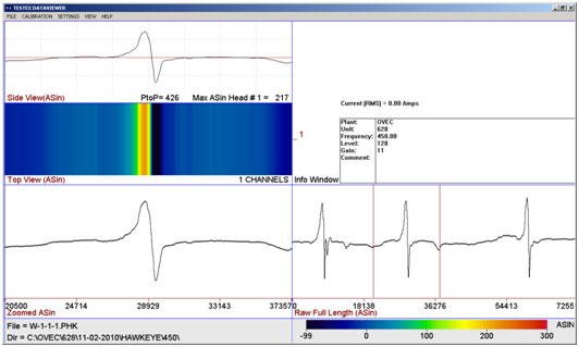
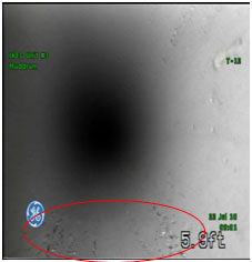
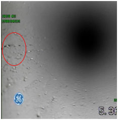
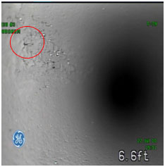
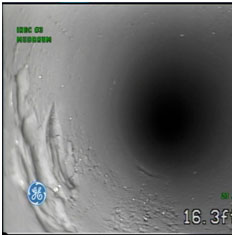
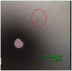
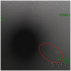
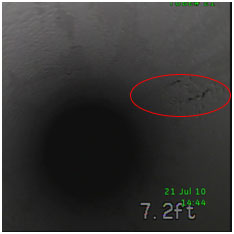
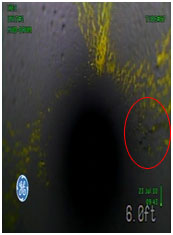
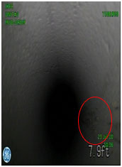
Waveforms from the EDM notches and from the tubes examined in the field can be found on the below and on the following pages. Pictures that were captured from the 2010 GE Inspections borescope examination are also shown next to the waveforms.


Section I: Modification of System
Several improvements were made to the probe in an effort to enable it to travel through the bends. Larger wheels were placed on the fingers of the front centering device to help the probe pass through butt welds. After the inspection, plant personnel sent TesTex actual bends cut out from this boiler so we could work with them to make sure we could get a probe through the bends. During the inspection, the BFET probe examined the straight tubes without any issues. The centering devices also needed to be modified to inspect the tubes with bends. Since this inspection, TesTex modified the centering fingers and was able to eliminate 2 sets of fingers which shortened the overall length of the probe to by 10”. The wheels on these fingers have also been enlarged, which should help the probe go past any butt welds it may encounter.The tailpiece on the probe was shortened 0.72”. The probe to poly connector cover was also shortened by 1.0”, and the material was switched from aluminum to a glass filled plastic. The outside diameter of the probe to poly connector was changed from a diameter of 2” to 1.69”. TesTex felt the glass filled plastic would have less friction with the tubes.
The original length of the poly that connects to the probe was 50’. During the inspection, our electronics and computers were set up approximately 20’ from the mud drum entrance. This restricted our ability to inspect all the desired tubes from one end and the system had to be torn down and set up on the other side. TesTex made new poly cables to a length of 100’ which allows all the tubes to be examined from one side.
Section J: Boiler #3 Inspection
On April 11-14, 2011, TesTex, Inc. examined 12 tubes with the newly developed Balanced Field Electromagnetic Technique (BFET) probe. Seven tubes showed cracking at the mud drum and the first 8 to 12” were examined. Elevations were taken with the zero point being at the mud drum tubesheet.Six of the tubes showed less than 25% deep cracking, four tubes showed 25% deep cracking, one tube showed 50% deep cracking and one tube showed 60% deep cracking.
TesTex attempted to insert the probe into Tube 93. At approximately 13’, the probe became hard to push. The video shows a weld at the location with additional weld metal on the ID. Our probe broke while pushing past this weld. The probe was repaired but this tube was not examined due to the indication selected from the video being the excess weld metal.
Tube 87 contains some large diameter pits. The Balanced Field Electromagnetic Technique is for sizing cracks and not pitting. A crack like indication was observed in the tube and was sized at 25% deep. It is possible that this indication is the edge of a pit.
TesTex was able to test the straight tubes and also the outside row tubes. We attempted to insert the probe into several tubes that contained the smaller bends but could not get the probe to go through the bends. It appears that the motor and slip ring housing is getting held up in the bend. TesTex has redesigned this housing to make it smaller. The OD of this housing was 2.0” during the inspection and has been modified to an OD of 1.68”.
At the time of the inspection, it was thought that our accuracy for the depth percentages provided was plus or minus 10%. This means a crack called 50% deep could be between 40% – 60% deep. The percentages provided assume the tube wall thickness at the location examined has a nominal wall thickness of 0.320”.
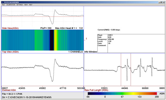
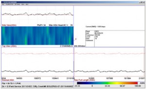
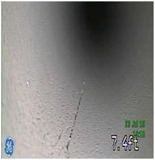
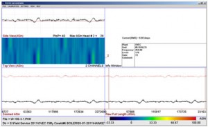
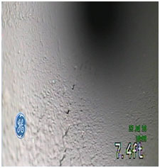
Waveforms collected during the inspection follow along with the pictures taken from the video that GE Inspections collected in July 2010.
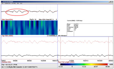
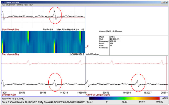
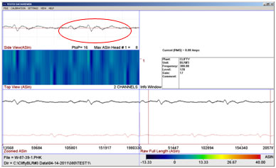
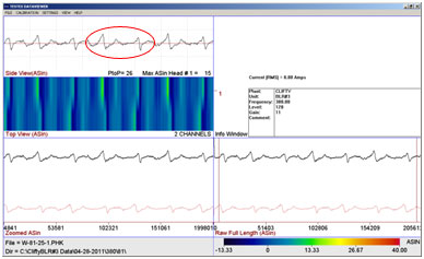
Tube 81 has two significant defects at this location. The four up/down peaks in each channel shows each crack twice. The sensors are 180˚ apart from each other which means these cracks are about 180˚ apart from each other. The Asin response for the largest flaw for channel 1 was 28 and the response for channel 2 was 20. Each defect was scanned twice in this waveform.
Results of Tube Samples
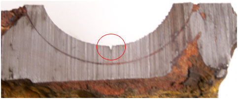
The sections of Tubes 73 and 81 that contained the cracks were cut out of the boiler and shipped to TesTex so the exact locations of the cracks could be identified. The calibration tubes and the samples were tested using our BFET probe. The Asin values for the calibration tubes and the waveforms collected at TesTex from the tubes 73 and 81 follow.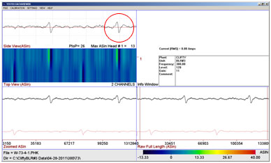
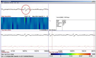
The waveform above is from Tube 73. This indication is located 56.5” from the end of the tube sample and sizes to be 50% deep with BFET. The defect was scanned twice by both sensors in this waveform. The picture above was taken with a borescope.
The waveform above is from Tube 81. This indication is located 30.5” from the end of the tube sample. This section contains two flaws that are approximately 180˚ apart. The smaller flaw was scanned four times and the larger defect was scanned three times by sensor one in this waveform. The large flaw, Flaw 1 sizes at approximately 60% deep and the smaller flaw, Flaw 2 sizes at 39% deep.
Both of these tubes contained several cracks. TesTex marked the location with the strongest indication for both tubes. The tube samples were sent to RJ Lee Group to physically have the depths of the cracks measured.
METALLURGY RESULTS:
The percentages of wall loss was based on a 0.320” wall thickness. Tube 73 was called 50% deep which translates to a crack depth of 0.160”. Tube 81 Flaw 1 was 60% deep which translates to a crack depth of 0.192” and Tube 81 Flaw 2 was 39% which translates to 0.125” deep. The results are shown in the following table.| Tube # | Depth reported by BFET | Actual Depth |
| 73 | 0.160” or 50% | 0.130” or 40.6% |
| 81 Flaw 1** | 0.192” or 60% | 0.118” or 36.9% |
| 81 Flaw 2 | 0.125” or 39% | 0.114” or 35.6% |
Tube 73 was overcalled by a crack depth percentage of 9.4, Tube 81 Flaw 1 was overcalled by a 23.1% crack depth, and Tube 81 Flaw 2 was overcalled by 3.4%.
TesTex plans to perform additional tests on sample tubes provided by Clifty Creek in an effort to improve our sizing. A borescope will be used to look for some cracks that are joining together. If any are found, the BFET flaw signals will be examined and the tubes can be split open to determine the actual depths.
Section K: Modification of System after Boiler #3 Inspection
The results of the Boiler #3 inspection showed that the probe development was improving but there were some items that needed to be improved. The overall diameter of the probe needed to be reduced to allow the probe to go through the bends in the middle row of tubes. The motors used to rotate the sensors contained spur gears and were wearing out quickly. There were a few places along the length of the probe where the wiring was exposed. Over time, the insulation on the wires would wear off and the wiring would short out or actually come apart at connection joints.The motor housing was the largest diameter section of the probe. The original motor used was not rugged enough to consistently provide the torque needed to rotate the BFET sensors. TesTex went through six motors during the Boiler #3 inspection. A smaller diameter motor with planetary gears that has four times the torque was chosen. The diameter of this new motor was 0.875” compared to the 1” diameter of the original probe. This allowed the motor housing to reduce from a diameter of 2” to 1.69”. The housing was changed from an open frame type to a sealed housing which helped protect the air hose and the wiring.
The original design had the wires and air hose running along the outside of the universal joints and the centering fingers. The TesTex Solution Providers Group designed universal joints with through holes that allowed the air hoses and the wiring to go through. This protected them from the wear on the tube and also the extra strain as the probe traveled through the bends. The air hose diameter went from .25” to 0.125”
The Clifty Creek Station had a mock-up of the drum and the bends manufactured and shipped to TesTex to test out the probe designs and perform duty cycles to help improve the probes reliability.
The universal joints allowed the probes to negotiate around the bends. The flexibility of the universal joints did not transfer the force needed to push the probe through the bends. Novel Springs were installed over top the universal joints to limit their range and help the universal joints flex back to their steady state position.
There were four probes built for future inspections in an effort to have the inspection team work uninterrupted. TesTex had two probes for the #3 Boiler inspection. When a probe malfunctions, TesTex has technicians onsite make repairs to the probe. There were times when both probes were in need of repair at the same time which reduced productivity. These repairs could take anywhere from ten minutes to six hours to complete.
Section L: Boiler #5 Inspection
On November 1 – 3, 2011, TesTex, Inc. examined 32 Front Wall Tubes with the newly developed Balanced Field Electromagnetic Technique (BFET) probe. Nineteen tubes showed cracking less than 25% deep, four tubes showed 25% deep cracking, four tubes showed 30% deep cracking, one tube showed 40% deep cracking, and three tubes showed 50% deep cracking.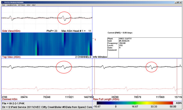
Waveforms collected during the inspection follow along with the pictures taken from the video that GE Inspections collected in July 2010.
The probes functioned properly during this inspection and no design changes were necessary for future inspections. Upon completion of the inspection, technicians made repairs to the probes and poly cables from the wear and tear of the inspection.
Section M: Inspection of Boiler #2
On April 9-12, 2012, TesTex, Inc. examined 45 Front Wall tubes in the #2 Boiler with the newly developed Balanced Field Electromagnetic Technique (BFET) probe. Twenty-five tubes showed cracking less than 25% deep, five tubes showed cracking 25% deep, five tubes showed cracking 30% deep, six tubes showed cracking 35% deep, two tubes showed cracking 40% deep, one tube showed 45% deep cracking, and three tubes showed 50% deep cracking.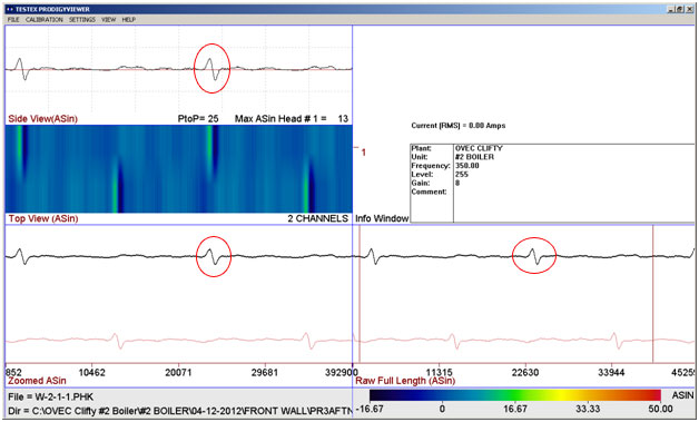

Section N: Current Status of System and Future Developments
With the probe design used at Clifty Creek, TesTex feels it can successfully test tubes with an inside diameter of 2” and greater and still be able to negotiate through some bends. There are small parts available to make the probes smaller. Unfortunately the probe design using a motor and slip ring within the probe body cannot go through bends in tubes with an inside diameter smaller than 2” due to the length of these parts.For smaller diameter tubes, TesTex has developed a probe that can examine straight runs of tubing. This probe design has a flexible shaft. The rotating motor is located at the electronics end of the probe. A slip ring is located on the probe end of the flexible shaft. The smallest inside diameter that this style probe has been used to examine is 1.24”.
An application for this probe design was to look for corrosion fatigue cracking with a width of 0.006”. These narrow cracks are difficult to detect with a borescope and TesTex was asked to develop a screening probe that could identify suspect cracks. These suspect cracks would then be proved up with a rotating BFET probe.
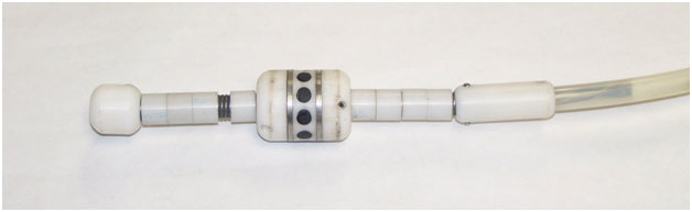
TesTex also developed a stationary BFET probe that is pulled through the tube as a screening tool. This probe has 10 BFET coils spaced circumferentially around the probe. A crack will produce an unbalanced signal. Any suspect signals will then be examined with a rotating BFET probe for flaw confirmation and depth sizing. In order to accurately size cracks with the Balanced Field Electromagnetic Technique, the coils need to bisect the crack at a 90˚ angle.
Section O: Conclusion
TesTex has performed five internal inspections for corrosion fatigue cracking to date. The experience gained has enabled improvements to the probes making them more reliable. Each size tube and wall thickness takes a specially design probe to ensure the BFET coils expand properly to fit inside the tube for optimal results. Through the use of calibration standards, the corrosion fatigue cracking can be sized within 10% accuracy.Through these projects, TesTex has the experience to design and manufacture rotating BFET probes for specific size tubes and for specific applications. Currently these inspections take a few months of preparation time and a joint effort between the client and TesTex. Through this joint effort the probes and inspection procedure can be developed properly for a successful inspection.
If you would like to learn more about our inspections, our systems, or how they can be used on your site, please contact us at 412.798.8990 or click here.